VanSpoof - Prototype 2 - Shrunken PCBs
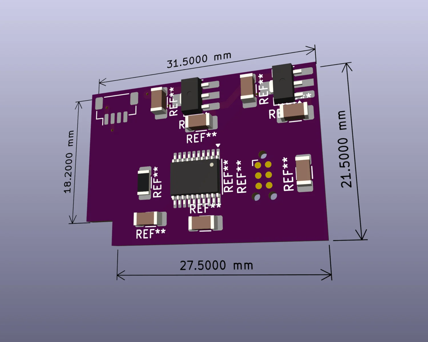
In my last post, about Low Tech Prototyping , I worked out the VanSpoof PCB had to be no bigger than 31.5 mm by 21.5 mm to fit in the space left over from removing the motor.
I wanted to reuse the existing wiring in the cable and e-shifter body, so I had to find sockets to match. I roughly measured the connectors on VanMoof's e-shifter at about a 1 mm pitch. I therefore guessed that they were likely to be JST-SH connectors , SHR-04V-S-B, going in to JST-SR headers, BM04B-SRSS-TB .
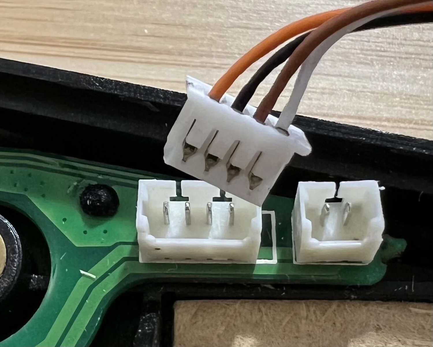
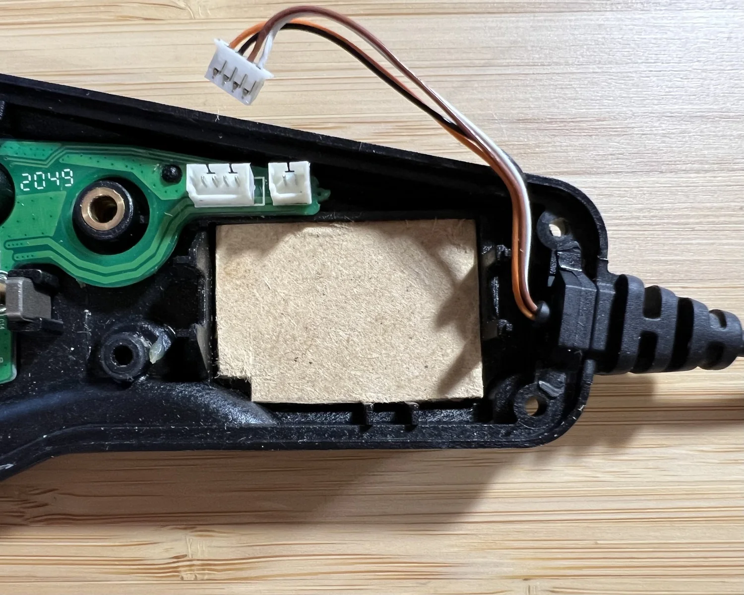
To make sure I didn't make a very costly mistake, ordering fresh PCBs with incorrect footprints, I thought I'd better pick up a couple of sockets to double-check.
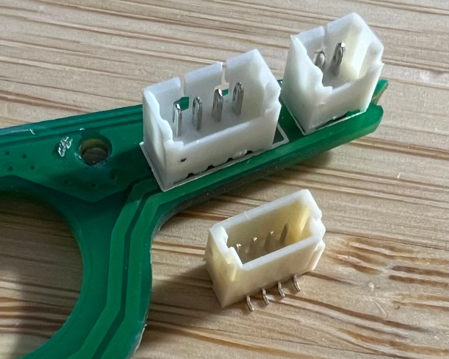
That beige component is my brand new JST socket. The original white sockets are definitely not the same size or pitch!
The old adage is if it's not JST then it's probably Molex! The closest pitch that Molex do is 1.25 mm , well within the tolerance of me eyeballing-it-with-some-digital-callipers.
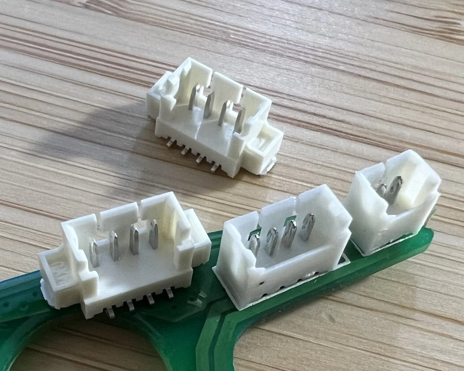
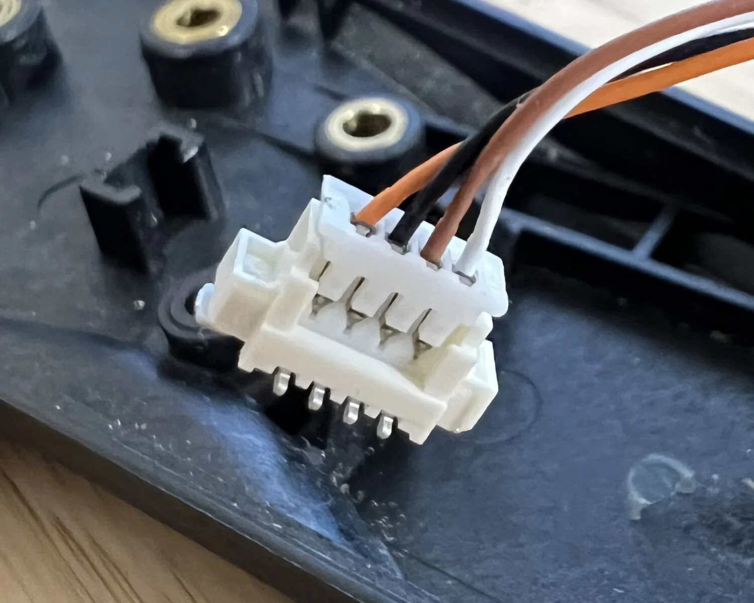
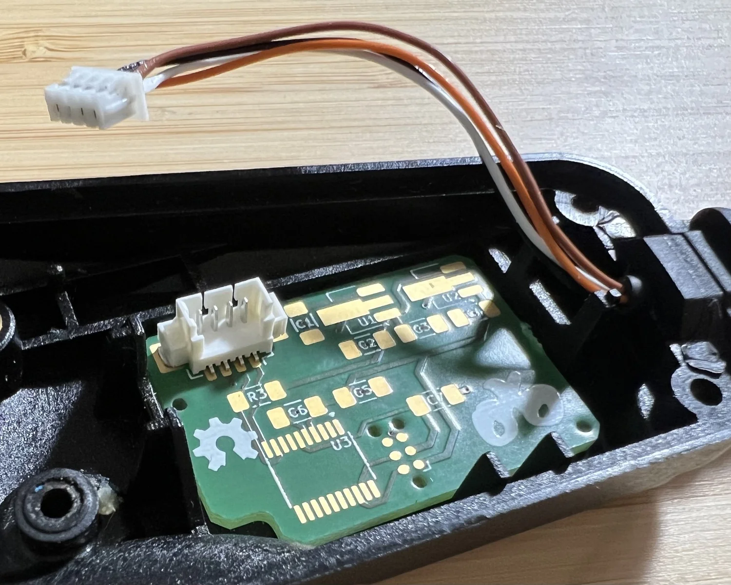
That's much better! The Molex sockets look like a much better fit, right down to the shape of the pins and cut-outs on their back wall.
For those playing along at home, the correct 4-wire socket for VanMoof e-shifters is a Molex PicoBlade series, 53398-0471 .
Unfortunately, Molex's SMD footprint is quite a bit wider than JST's, so the board needed a fair bit of layout work to make everything fit.
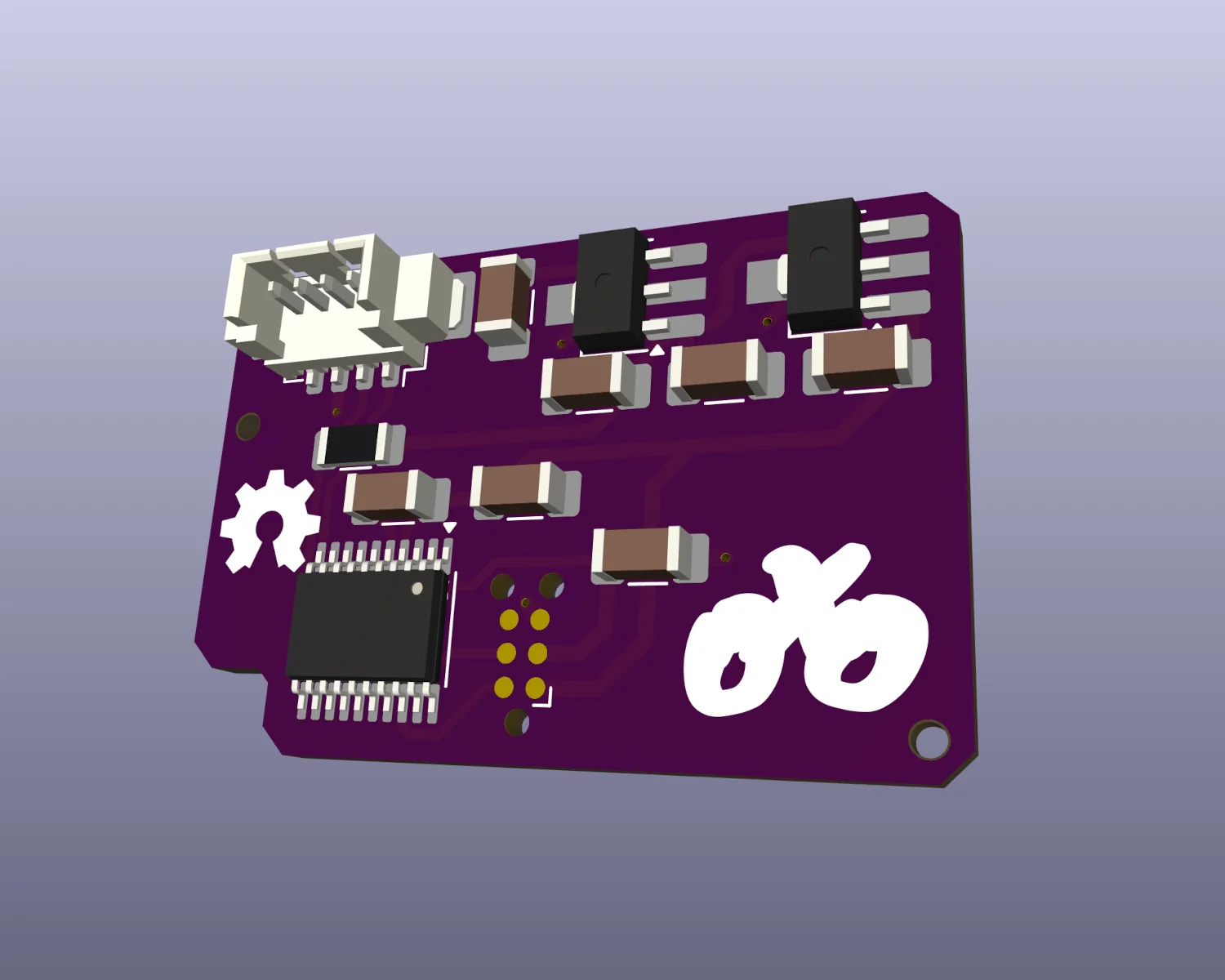
With the socket and its footprint confirmed and the board laid out I could now happily, and safely, order my new PCBs.
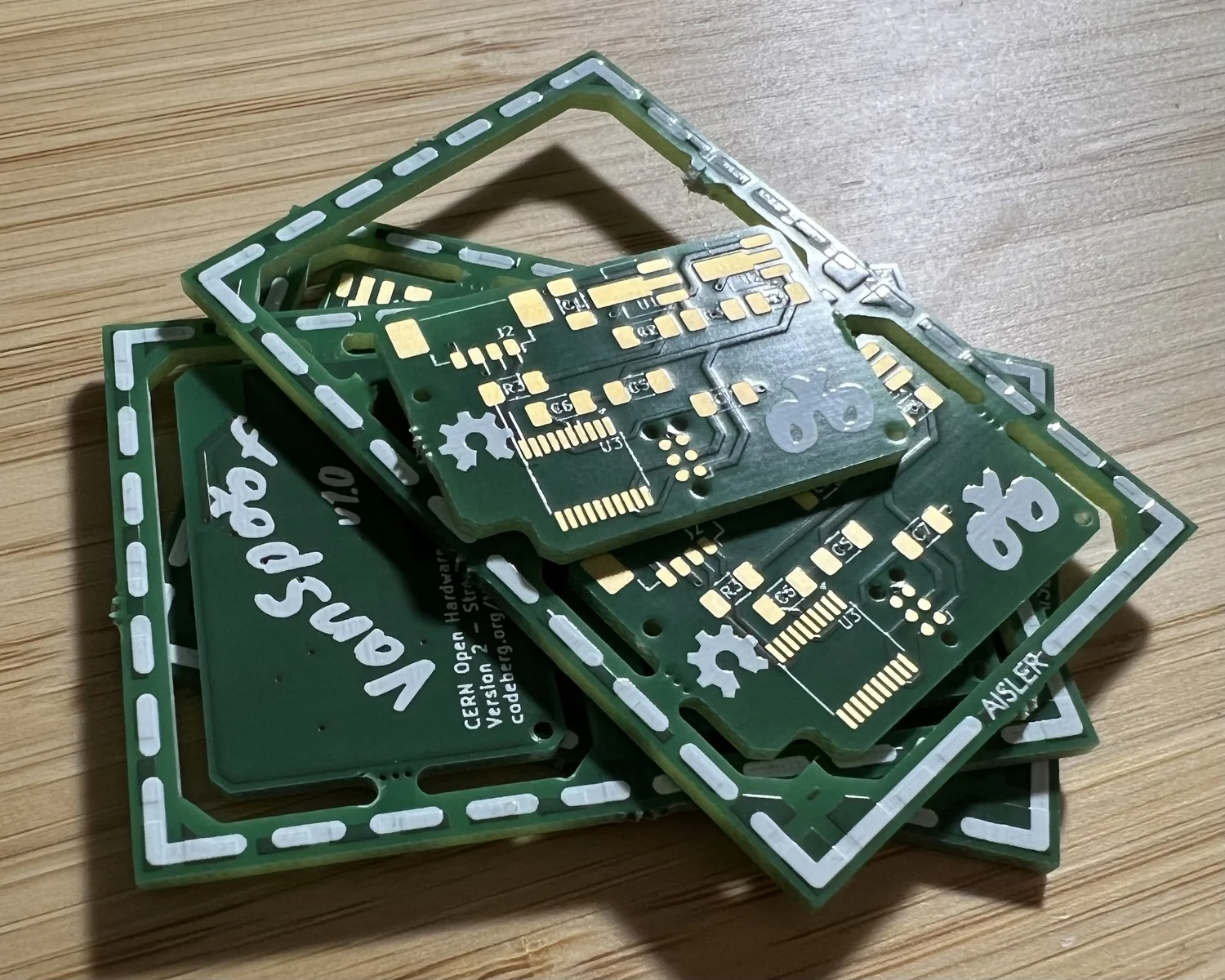
Checking the new board for fit against the Low-Tech MDF prototype proves my measurements accurate. The PCB nestles snugly into the space left by the old motor.
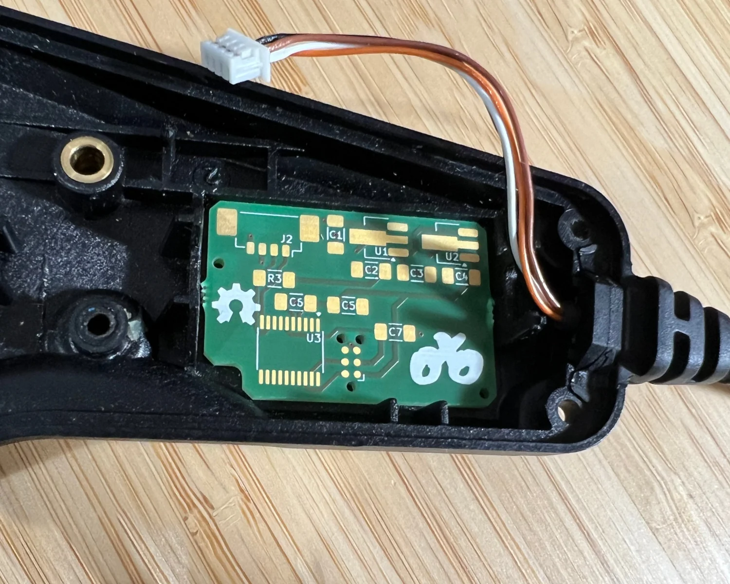
Placing one of the demo Molex sockets from earlier on to the board gives an idea of how it will look, fully assembled.
It also triple-check confirms I picked the correct footprint for the layout. Phew!
2025-04-08